
10/14 - 10/17
- Oct 17, 2025
- 2 min read
I started this week off by finally soldering my entire pcb, it took most of class since there are a lot of parts, so I only got to test it at the very end of class on tuesday, but it didnt seem to work, so I needed to test it with a multimeter, I suspected the hall effect sensor was not working, so I decided that I would replace it.

The next day, I worked on soldering on a new sensor, and this time I added heatshrinks, since the wires are pretty close together, and since they would be going in an enclosed space, I wanted to protect it from getting fried. I attached it, and it responded to the magnet when I checked on the multimeter, which was a good sign.

I then tried to figure out what else was wrong, since everything else seemed to work, but there was still no current going through the electromagnet. I looked back to the pcb designs to see if there was anything I messed up while soldering. When I checked, I couldn't really see what the issue was, but the voltage regulator kept getting really hot, so I figured that was probably what was wrong. I decided to take it off the pcb and replace it.

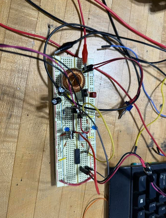
When I was trying to take it off, though, I accidentally messed up the middle pad that went to the voltage regulator, but it wasn't much of an issue since I had wanted to try again with a new PCB anyway. I got all the parts I would need, and this time I decided to put them on a breadboard before I soldered them in, so I could see that they all worked and wouldnt have to troubleshoot againb.


At the end opf thursday I got everything connected, but it still wasnt working, although the mosfet was getting really hot and there was more amps flowing through the circuit then when i previously constructed it. I didn't get to do too many tests with it, but hopefully I should be able to fix the issue pretty quickly.


Comments